leafman60
Cruisin' Guzzisti
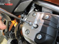
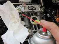
Start by blowing all loose dirt or grime away before loosening any fasteners or parts. This helps avoid debris finding its way into the internals.
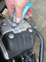
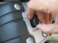
Next, pry out the little “Moto Guzzi” emblems. This may take more effort than you’d think if you had good dealer prep. My dealer mechanic had added some glue to the underside of the emblems to avoid the common problem of lost emblems. I used a thin- blade utility knife as a prying tool and worked the emblem out. You have to get it up and then pull it loose from the glue. I know that I’m kinda anal sometimes but I applied blue tape so as not to mar the plug wire retainer when I pried out the emblem.
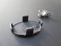
This is what the little emblem looks like from behind. The blob of glue is in the background. Once the embem is out, you remove the retaining screw and the small spark plug wire cover piece.
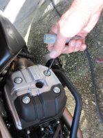
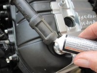
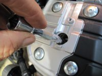
Next is removal of the spark plug boot from the plug. Much has been written about this and several people have mutilated a plug wire/boot trying to remove it from the plug. The shop manual says to insert a screwdriver through the rear fin opening and pry the boot up. This is easier said than done. The throttle body and the injector kinda get in the way.
I discovered that I could grab the boot and rotate it left and right several times to break loose its seal to the valve cover. Then, by twisting it a bit further the shoulder of the boot rides up on the valve cover with the effect of pulling the boot off the plug. Help it with your fingers and it comes right off. You can also slip a nylon zip-tie or a piece of strong twine etc around the boot head and pull it off.
Then take a long socket extension and a thin wall socket to reach the spark plug. This is the same size socket as used to remove the plugs on the current BMW boxers. I use a Duralast 16mm deep that I bought from Autozone Parts. If the wall of the socket is too thick, the socket will not go down into the valve cover.
My socket did not have a rubber retainer inside so, once the plug was loose, I removed it from the well with a telescopic magnet.
Next, remove the valve cover retaining bolts. Rubber washers are under them.
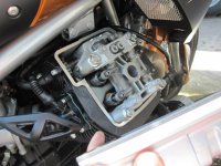
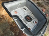
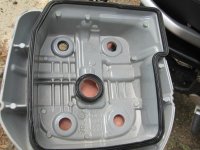
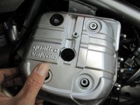
Then, remove the plastic heat guard that covers the rear of the valve cover and lift away the valve cover.
Just look at those easy-to-adjust rocker arms. Ducati people, eat your hearts out.
The valve cover gaskets are rubber and re-useable after wiping clean.
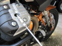
Now, we have to get the piston to top-dead-center on the compression stoke so that all valves will be closed and the rocker arms off the heel of the cam with the valve lash present. You can manually turn the rear wheel with the transmission in gear or you can put a 24 mm socket on the front crank nut.
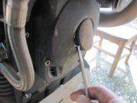
First, pry off the rubber plug on the front of the engine to reveal the nut. Then use the socket and ratchet to turn the engine.
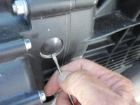
Indicators are supposedly on on the flywheel, as with all Guzzi models, to indicate when each piston is at TDC but they are not as obvious as on the older engines. You may want to paint a white mark on the flywheel once you have the proper TDC position. First, remove the rubber plug on the rider’s right side behind the motor so you can see the flywheel.
Another way to find TDC, upon which I relied, is to insert something soft like a soda straw into the spark plug hole to rest on top of the piston and move with the piston. You just turn the engine with the wrench and watch the soda straw until it shows the piston reaching the top of its stroke. On the anal side, I like to come to rest at TDC as the crank would normally turn and not “back it up” to rest at my adjustment point. The theory here is to have the cam chain taut and not let any cam chain slack interfere with your adjustment points. The engine crank turns in a clockwise direction if you are standing in front of the bike and looking back at the front of the motor. Looking in the flywheel peephole, the normal direction of rotation would show the flywheel moving upward.
Remember that you want the piston at TDC on the compression stroke. You can watch the valves to figure this out. When the piston comes to the top and all four valves are closed, that’s what you want. You can verify this by grabbing the rockers and shaking them. You’ll feel them a little loose. You can also double-check by looking for the flywheel mark.
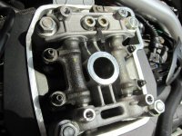
Before using the feeler gauges to check the lash, I like to squirt a little cleaner solvent (brake cleaner etc) on the lash joint to clean-out any oil that may interfere with a good gauge feel. After completing the valve adjust, squirt a little oil back into the valve lash gap. Intake is .006 inch, .15 mm. Exhaust is .008 inch, .20mm.
The intake valves are on the rear, near the intake. Exhaust valves are on the front where the exhaust pipe is.
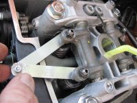
This is a procedure held over from my many years of BMW valve adjusting. BMW recommends checking clearances with two feeler gauges at once. The theory is that slop in the rocker shaft can alter your readings so you want to insert a feeler gauge on both valve trains to take out such free play. I don’t know if it’s worth the trouble but I am used to doing it.
You still check and adjust each valve separately but you do so with a feeler gauge on the other valve while you’re doing it. You can also try to bridge one feeler gauge blade across both valves.
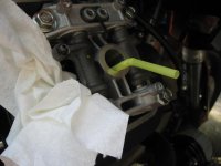
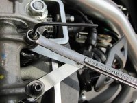
Now, we do the exhaust. So simple. Loosen the lock nut, adjust the allen stud. You do have to play with it. When you tighten the lock nut, your clearance may change a wee bit due to pulling the slack out of the threads. You’ll have to back it off and work it until you get what you want after tightening down the lock nut. Play with it and you’ll get it correct. You want a slight drag on the feeler gauge. If you are in doubt, take the next size up feeler gauge and see if it will go in your gap. If it does, you had them too loose. Of course, remember- too loose, is better than too tight.
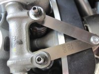
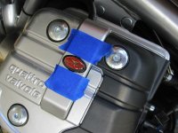
Another look at the exhaust side after we have adjusted both valves to proper spec.
After one cylinder is completed, you move to the other side and repeat the procedure outlined above. Get the piston to TDC and be sure all valves are closed and you can feel slack in the rockers that you’ll be adjusting.
In keeping with being very detailed, I like to squirt a little oil back into the adjusted joints after the lash adjustment is completed.
Wipe the valve cover gaskets clean and replace them on the cylinder head.
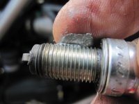
Before replacing the spark plugs, examine them. Clean or replace if necessary. Guzzi uses the twin point plugs like BMW. I like to dab a wee bit of anti-seize compound on the threads.
Insert the plug into the well with your plug socket or, as shown here, the extension magnet. Torque plug to specs.
I like to lube up the interior and exterior of the plug boot with some dielectric grease to ease that boot removal procedure we discussed at the beginning.
Position the valve cover on the head.
After replacing the plastic heat guard, rubber washers, valve cover screws, and the spark plug wire cover, add a dab of silicone or some sort of glue to hold down that little MG emblem and re-insert the emblem.
That’s all there is to it.
Next, pry out the little “Moto Guzzi” emblems. This may take more effort than you’d think if you had good dealer prep. My dealer mechanic had added some glue to the underside of the emblems to avoid the common problem of lost emblems. I used a thin- blade utility knife as a prying tool and worked the emblem out. You have to get it up and then pull it loose from the glue. I know that I’m kinda anal sometimes but I applied blue tape so as not to mar the plug wire retainer when I pried out the emblem.
This is what the little emblem looks like from behind. The blob of glue is in the background. Once the embem is out, you remove the retaining screw and the small spark plug wire cover piece.
Next is removal of the spark plug boot from the plug. Much has been written about this and several people have mutilated a plug wire/boot trying to remove it from the plug. The shop manual says to insert a screwdriver through the rear fin opening and pry the boot up. This is easier said than done. The throttle body and the injector kinda get in the way.
I discovered that I could grab the boot and rotate it left and right several times to break loose its seal to the valve cover. Then, by twisting it a bit further the shoulder of the boot rides up on the valve cover with the effect of pulling the boot off the plug. Help it with your fingers and it comes right off. You can also slip a nylon zip-tie or a piece of strong twine etc around the boot head and pull it off.
Then take a long socket extension and a thin wall socket to reach the spark plug. This is the same size socket as used to remove the plugs on the current BMW boxers. I use a Duralast 16mm deep that I bought from Autozone Parts. If the wall of the socket is too thick, the socket will not go down into the valve cover.
My socket did not have a rubber retainer inside so, once the plug was loose, I removed it from the well with a telescopic magnet.
Next, remove the valve cover retaining bolts. Rubber washers are under them.
Then, remove the plastic heat guard that covers the rear of the valve cover and lift away the valve cover.
Just look at those easy-to-adjust rocker arms. Ducati people, eat your hearts out.
The valve cover gaskets are rubber and re-useable after wiping clean.
Now, we have to get the piston to top-dead-center on the compression stoke so that all valves will be closed and the rocker arms off the heel of the cam with the valve lash present. You can manually turn the rear wheel with the transmission in gear or you can put a 24 mm socket on the front crank nut.
First, pry off the rubber plug on the front of the engine to reveal the nut. Then use the socket and ratchet to turn the engine.
Indicators are supposedly on on the flywheel, as with all Guzzi models, to indicate when each piston is at TDC but they are not as obvious as on the older engines. You may want to paint a white mark on the flywheel once you have the proper TDC position. First, remove the rubber plug on the rider’s right side behind the motor so you can see the flywheel.
Another way to find TDC, upon which I relied, is to insert something soft like a soda straw into the spark plug hole to rest on top of the piston and move with the piston. You just turn the engine with the wrench and watch the soda straw until it shows the piston reaching the top of its stroke. On the anal side, I like to come to rest at TDC as the crank would normally turn and not “back it up” to rest at my adjustment point. The theory here is to have the cam chain taut and not let any cam chain slack interfere with your adjustment points. The engine crank turns in a clockwise direction if you are standing in front of the bike and looking back at the front of the motor. Looking in the flywheel peephole, the normal direction of rotation would show the flywheel moving upward.
Remember that you want the piston at TDC on the compression stroke. You can watch the valves to figure this out. When the piston comes to the top and all four valves are closed, that’s what you want. You can verify this by grabbing the rockers and shaking them. You’ll feel them a little loose. You can also double-check by looking for the flywheel mark.
Before using the feeler gauges to check the lash, I like to squirt a little cleaner solvent (brake cleaner etc) on the lash joint to clean-out any oil that may interfere with a good gauge feel. After completing the valve adjust, squirt a little oil back into the valve lash gap. Intake is .006 inch, .15 mm. Exhaust is .008 inch, .20mm.
The intake valves are on the rear, near the intake. Exhaust valves are on the front where the exhaust pipe is.
This is a procedure held over from my many years of BMW valve adjusting. BMW recommends checking clearances with two feeler gauges at once. The theory is that slop in the rocker shaft can alter your readings so you want to insert a feeler gauge on both valve trains to take out such free play. I don’t know if it’s worth the trouble but I am used to doing it.
You still check and adjust each valve separately but you do so with a feeler gauge on the other valve while you’re doing it. You can also try to bridge one feeler gauge blade across both valves.
Now, we do the exhaust. So simple. Loosen the lock nut, adjust the allen stud. You do have to play with it. When you tighten the lock nut, your clearance may change a wee bit due to pulling the slack out of the threads. You’ll have to back it off and work it until you get what you want after tightening down the lock nut. Play with it and you’ll get it correct. You want a slight drag on the feeler gauge. If you are in doubt, take the next size up feeler gauge and see if it will go in your gap. If it does, you had them too loose. Of course, remember- too loose, is better than too tight.
Another look at the exhaust side after we have adjusted both valves to proper spec.
After one cylinder is completed, you move to the other side and repeat the procedure outlined above. Get the piston to TDC and be sure all valves are closed and you can feel slack in the rockers that you’ll be adjusting.
In keeping with being very detailed, I like to squirt a little oil back into the adjusted joints after the lash adjustment is completed.
Wipe the valve cover gaskets clean and replace them on the cylinder head.
Before replacing the spark plugs, examine them. Clean or replace if necessary. Guzzi uses the twin point plugs like BMW. I like to dab a wee bit of anti-seize compound on the threads.
Insert the plug into the well with your plug socket or, as shown here, the extension magnet. Torque plug to specs.
I like to lube up the interior and exterior of the plug boot with some dielectric grease to ease that boot removal procedure we discussed at the beginning.
Position the valve cover on the head.
After replacing the plastic heat guard, rubber washers, valve cover screws, and the spark plug wire cover, add a dab of silicone or some sort of glue to hold down that little MG emblem and re-insert the emblem.
That’s all there is to it.
Attachments
-
 LeafmanStelv-ValvAdj1.jpg69.6 KB · Views: 2,268
 -
 LeafmanStelv-ValvAdj2.jpg94.9 KB · Views: 2,261
 -
 LeafmanStelv-ValvAdj3.jpg65.9 KB · Views: 2,276
 -
 LeafmanStelv-ValvAdj4.jpg74.6 KB · Views: 2,275
 -
 LeafmanStelv-ValvAdj5.jpg60.3 KB · Views: 2,262
 -
 LeafmanStelv-ValvAdj6.jpg44 KB · Views: 2,267
 -
 LeafmanStelv-ValvAdj7.jpg49.4 KB · Views: 2,281
 -
 LeafmanStelv-ValvAdj8.jpg41.5 KB · Views: 2,273
 -
 LeafmanStelv-ValvAdj9.jpg53.8 KB · Views: 2,269
 -
 LeafmanStelv-ValvAdj10.jpg73.1 KB · Views: 2,286
 -
 LeafmanStelv-ValvAdj11.jpg69.2 KB · Views: 2,268
 -
 LeafmanStelv-ValvAdj12.jpg55 KB · Views: 2,267
 -
 LeafmanStelv-ValvAdj13.jpg61.8 KB · Views: 2,258
 -
 LeafmanStelv-ValvAdj14.jpg43.7 KB · Views: 2,262
 -
 LeafmanStelv-ValvAdj15.jpg61.6 KB · Views: 2,260
 -
 LeafmanStelv-ValvAdj16.jpg56 KB · Views: 2,263
 -
 LeafmanStelv-ValvAdj17.jpg88.3 KB · Views: 2,259
 -
 LeafmanStelv-ValvAdj18.jpg51.5 KB · Views: 2,255
 -
 LeafmanStelv-ValvAdj01.jpg62.6 KB · Views: 2,253
 -
 LeafmanStelv-ValvAdj02.jpg81 KB · Views: 2,258
 -
 LeafmanStelv-ValvAdj03.jpg62.7 KB · Views: 2,253
 -
 LeafmanStelv-ValvAdj04.jpg58.4 KB · Views: 2,252