Thanks to Patrick Hayes/iainw & Mike H @MPHCycles.com:
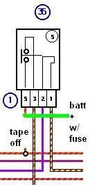
The graphic above should explain the improvement.
Look at the relay diagram which is item #36 above. That little "P" shaped circuit on the right, fed by pins 1 and 2, is the relay's internal operating electromagnet coil. Not much work there.
Now look at the 'bridge' connection circuit fed by pins 3 an 5. When the electromagnet is energized, it pulls that "T" shaped device against the two internal connectors and bridges or 'makes' the connection. Pin 3 now feeds electrons out to your starter solenoid. The electrons come in via pin 5. But, that pin 5 source does several other things as well and has to pass through numerous connector blocks before getting here. We loose a little bit of power at every connector. Eventually, even though we still supply 12 volts to the solenoid, we no longer provide enough amperage to actually throw the heavy electromagnet in the solenoid. Thus, all we get is the 'click' of the relay itself.
If we simply provide a direct circuit from the battery into pin 5, we haven't changed anything about the operation of the relay, only the source of electrons which we will feed to the solenoid.
Tape, or a crimp dead-end cover to the wire harness. Whatever you prefer just to be sure it doesn't short to ground.
After spending quite some time on a few of them recently I offer these suggestions;
The CARC bikes have the same problem as the small blocks that exhibit this symptom, but a slightly different fix is possible.
The basic issue is a voltage drop on the positive side, from battery to the starter relay. On the bikes I have been measuring, we see as much as a 4.0 volt loss. This obviously makes it hard for the relay deliver the amperage needed to engage the starter solenoid reliably.
The small block needs a power supply relay added in to deliver full 12V to the starter relay supply side.
This is simple enough to do by removing the orange wire from the starter relay socket, plugging it to the 85 terminal on the new relay. 86 goes to a GOOD ground. 30 goes to battery positive, 87 goes to the original starter relay in the hole where the orange wire was removed. What this does is use the stock wiring only to close the relay instead of supply the power for the load. This should also help eliminate the starter fuse blowing at random times.
This circuit is easily "supplemented" by an additional wire, paralleling the circuit from near the fuse box green/red wire to the bike side of the ignition switch connector. At this connector there is an inexplicable size drop in the wire. I dont have pics of the bike after the additional wiring is done for this one. Edit: Mike offers a plug-in jumper to handle this issue. Contact him direct at MPHCycles.com -- Todd
It works for me, if you try it on your bike, use common sense regarding materials, routing, fusing etc. If this sounds like more than you are comfortable doing, than don't do it. Use the info to assist the Tech who does it for you.
Patrick Hayes' small block solution:

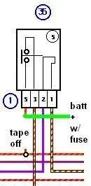
The graphic above should explain the improvement.
Look at the relay diagram which is item #36 above. That little "P" shaped circuit on the right, fed by pins 1 and 2, is the relay's internal operating electromagnet coil. Not much work there.
Now look at the 'bridge' connection circuit fed by pins 3 an 5. When the electromagnet is energized, it pulls that "T" shaped device against the two internal connectors and bridges or 'makes' the connection. Pin 3 now feeds electrons out to your starter solenoid. The electrons come in via pin 5. But, that pin 5 source does several other things as well and has to pass through numerous connector blocks before getting here. We loose a little bit of power at every connector. Eventually, even though we still supply 12 volts to the solenoid, we no longer provide enough amperage to actually throw the heavy electromagnet in the solenoid. Thus, all we get is the 'click' of the relay itself.
If we simply provide a direct circuit from the battery into pin 5, we haven't changed anything about the operation of the relay, only the source of electrons which we will feed to the solenoid.
Tape, or a crimp dead-end cover to the wire harness. Whatever you prefer just to be sure it doesn't short to ground.
iainw said:On an 05 Breva 1100 the wire to cut and take to the battery is pin 3 the yellow wire, and not pin 5 the orange/yellow wire.
This issue is well known and very well documented by many owners on this forum and others.Mike @MPHCycles small block:
After spending quite some time on a few of them recently I offer these suggestions;
The CARC bikes have the same problem as the small blocks that exhibit this symptom, but a slightly different fix is possible.
The basic issue is a voltage drop on the positive side, from battery to the starter relay. On the bikes I have been measuring, we see as much as a 4.0 volt loss. This obviously makes it hard for the relay deliver the amperage needed to engage the starter solenoid reliably.
The small block needs a power supply relay added in to deliver full 12V to the starter relay supply side.
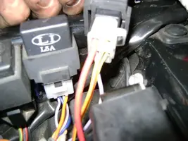
This is simple enough to do by removing the orange wire from the starter relay socket, plugging it to the 85 terminal on the new relay. 86 goes to a GOOD ground. 30 goes to battery positive, 87 goes to the original starter relay in the hole where the orange wire was removed. What this does is use the stock wiring only to close the relay instead of supply the power for the load. This should also help eliminate the starter fuse blowing at random times.
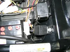
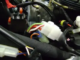
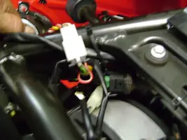
On the CARC bikes, we have seen a similar voltage drop in the circuit that feeds the ignition switch (yellow on these bikes). After making sure the plug for the ignition switch, battery terminals and chassis ground are clean and tight, there was still a drop of 2.2 volts by the time the juice gets to the starter relay. It seems there is a splice in the harness (in the area of the harness shown), where the lead from where the alternator is joined to the ignition switch circuit.Mike @MPHCycles CARC Fix:
This circuit is easily "supplemented" by an additional wire, paralleling the circuit from near the fuse box green/red wire to the bike side of the ignition switch connector. At this connector there is an inexplicable size drop in the wire. I dont have pics of the bike after the additional wiring is done for this one. Edit: Mike offers a plug-in jumper to handle this issue. Contact him direct at MPHCycles.com -- Todd


It works for me, if you try it on your bike, use common sense regarding materials, routing, fusing etc. If this sounds like more than you are comfortable doing, than don't do it. Use the info to assist the Tech who does it for you.

