Stelvio Install Guide for the PC-V and AutoTune module
Notes:
1. Remove seat.
2. Lay the PC-V on the airbox and route the PC-V wires to each side throttle bodies. On the small tank models, plastics must be removed. On big tank models, simply unbolt the battery hold down, and slide battery back with the rubber tray.
The side with the single grey wire goes to the right side (on bike) Throttle Position Sensor (TPS)/injector body.
3. Disconnect the injector plug by pushing down on the wired clip and pull off:
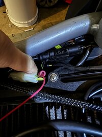
4. Next unplug the TPS plug. This is the plug that sits atop the right side throttle body. The plug (shown below) is a three-wire plug *NOT* four wire. Once found and unplugged, locate the red wire in the TPS plug, and fasten the Posi-tap connector to this wire as shown below. Re-connect TPS plug when done.
5. Install the injector plugs next. Male to OEM connector and female to injector from the PC-V harness:
Be sure that all plugs are routed away from high-heat sources and free of throttle cable and linkage.
6. For those installing the AutoTune module (ONLY WITH GTM ECU FLASH), remove the stock 02-sensor, and install the new Bosch wide-band sensor into the exhaust. Connect the AutoTune lead (to the new 02-sensor) and run/fasten the wire alongside of the others as shown below, then up and between the air-box and frame rails. The fused connector/plug from the new sensor can be zip-tied to the bottom of the frame. Allow some slack in the cable from the sensor. Be sure it's clear of the swingarm pivot/pinch points.
7. AutoTune requires an ignition key switched 12v source - The tag light wire is a good one. This is best found under the right small side cover shown below using the supplied Posi-tap connector - verify with a voltmeter for battery voltage when key is on, and zero when off.

8. Next install the six (6) colored 02-sensor wires into the AutoTune unit as described in the provided instructions. You can (re-)connect the supplied jumper cable from the AutoTune to the PC-V at this time, and also all of the rubber plugs (screw holes and ports) into both PC and AT units. Both the PC-V and the AutoTune can be grounded to the battery ground. Be sure to route both the PC-V and AutoTune harness so that they are clear of pinch points. Shown below is both units with the GTM CNC air-box ring installed.
On the 2010 Stelvio, PC-V wiring needs to be routed along the left side of the battery. Placement of the PC-V/AT is completely up to you, just be sure it clears the seat bumpers and related. If the GTM air box ring is used, on the back of the air box behind where the ring leaves the air-box exposed is achievable.
9. Re-install all body parts, checking to be sure all connections are free and clear of high-heat and pinch points. I'll post on the Forum on the operation of both PC-V and AutoTune.
10. Ride, and note any problematic areas... Retrieve, save and send the map to us (if purchased from us) for us to tweak.
Notes:
1. Remove seat.
2. Lay the PC-V on the airbox and route the PC-V wires to each side throttle bodies. On the small tank models, plastics must be removed. On big tank models, simply unbolt the battery hold down, and slide battery back with the rubber tray.
The side with the single grey wire goes to the right side (on bike) Throttle Position Sensor (TPS)/injector body.
3. Disconnect the injector plug by pushing down on the wired clip and pull off:
4. Next unplug the TPS plug. This is the plug that sits atop the right side throttle body. The plug (shown below) is a three-wire plug *NOT* four wire. Once found and unplugged, locate the red wire in the TPS plug, and fasten the Posi-tap connector to this wire as shown below. Re-connect TPS plug when done.
5. Install the injector plugs next. Male to OEM connector and female to injector from the PC-V harness:
Be sure that all plugs are routed away from high-heat sources and free of throttle cable and linkage.
6. For those installing the AutoTune module (ONLY WITH GTM ECU FLASH), remove the stock 02-sensor, and install the new Bosch wide-band sensor into the exhaust. Connect the AutoTune lead (to the new 02-sensor) and run/fasten the wire alongside of the others as shown below, then up and between the air-box and frame rails. The fused connector/plug from the new sensor can be zip-tied to the bottom of the frame. Allow some slack in the cable from the sensor. Be sure it's clear of the swingarm pivot/pinch points.
7. AutoTune requires an ignition key switched 12v source - The tag light wire is a good one. This is best found under the right small side cover shown below using the supplied Posi-tap connector - verify with a voltmeter for battery voltage when key is on, and zero when off.
8. Next install the six (6) colored 02-sensor wires into the AutoTune unit as described in the provided instructions. You can (re-)connect the supplied jumper cable from the AutoTune to the PC-V at this time, and also all of the rubber plugs (screw holes and ports) into both PC and AT units. Both the PC-V and the AutoTune can be grounded to the battery ground. Be sure to route both the PC-V and AutoTune harness so that they are clear of pinch points. Shown below is both units with the GTM CNC air-box ring installed.
On the 2010 Stelvio, PC-V wiring needs to be routed along the left side of the battery. Placement of the PC-V/AT is completely up to you, just be sure it clears the seat bumpers and related. If the GTM air box ring is used, on the back of the air box behind where the ring leaves the air-box exposed is achievable.
9. Re-install all body parts, checking to be sure all connections are free and clear of high-heat and pinch points. I'll post on the Forum on the operation of both PC-V and AutoTune.
10. Ride, and note any problematic areas... Retrieve, save and send the map to us (if purchased from us) for us to tweak.