• Ciao Guest - You’ve landed at the ultimate Guzzi site. NEW FORUM REGISTRATIONS REQUIRE EMAIL ACTIVATION - CHECK YOUR SPAM FOLDER - Use the CONTACT above if you need help. New to the forum? For all new members, we require ONE post in the Introductions section at the bottom, in order to post in most of the other sections. ALWAYS TRY A SEARCH BEFORE STARTING A NEW TOPIC - Most questions you may have, have likely been already answered. DON'T BE A DRIVE-BY POSTER: As a common courtesy, check back in and reply within 24 hours, or your post will be deleted. Note there's decades of heavily experienced Guzzi professionals on this site, all whom happily give endless amounts of their VALUABLE time for free; BE COURTEOUS AND RESPECTFUL!
  • Be sure to see the GTM STORE link also above for our 700+ product inventory, including OEM parts and many of our 100% Made-in-SoCal-USA GTM products and engine kits. In SoCal? Click the SERVICE tab above for the best in service, tires, tuning and installation of our products or custom work, and don't miss our GT MotoCycles® (not) art on the BUILDS tab above. WE'RE HERE ONLINE ONLY - NO PHONE CALLS MADE OR RECEIVED - DO NOT EMAIL AND ASK QUESTIONS OR ASK TO CALL YOU.
  • There is ZERO tolerance on personal attacks and ANY HYPERLINKS to PRODUCT(S) or other competing website(s), including personal pages, social media or other Forums. This ALSO INCLUDES ECU DIAGnostic software, questions and mapping. We work very hard to offer commercially supported products and to keep info relevant here. First offense is a note, second is a warning, third time will get you banned from the site. We don't have the time to chase repeat (and ignorant) offenders. This is NOT a social media platform; It's an ad-free, privately funded website, in small help with user donations. Be sure to see the GTM STORE link above; ALL product purchases help support the site, or you can upgrade your Forum profile or DONATE via the link above.

Turn signal conundrum

Nathan Stanley

Just got it firing!
Joined
May 10, 2020
Messages
19
Reaction score
4
Location
Las Vegas
Working out the problems in the electrics on my ‘75 850t. One of the PO’s removed all the turn signals and bastardized the associated wiring in the process (along with starter, horn, and brake light wiring). Everything worked as wired, it just wasn’t technically accurate, and the provisions for signals had all been stripped out.
Do all turn signal circuits need to be connected and working for any/all of them to operate? For instance, if the idiot lights are disconnected, will the signals still work? Or if both left signals are disconnected, will the right side still work?
I have the right side signals connected as correctly as I can manage, based on the wiring diagram, and I can hear the flashing unit click when I switch “off” the turn signals. They aren’t Illuminating. Should the flashing unit be making more audible noise? The signals illuminate when wired directly to the battery.
 
The idiot lights don't matter in that the system will work without them.
So long as you have both lights (front and back) on one side then that side should work.
The system is quite simple, power through the flasher relay then on to the indicator switch. Power then goes to both lights in parallel, and the current flowing makes the relay flash. You can normally hear it clicking.
 
I believe I have a grounding(earth) fault somewhere. I changed the grounding locations on both signals and now they work. Also, I’m getting about 300 millivolts across the positive and ground connections for the signals, with the switch off. Shouldn’t it be closer to zero?
Also, the front signal is significantly dimmer than the rear.
 
Last edited:
I don't know if they all have to be the same but the total resistance of the Circuits need to be sufficient to trigger the *Flasher*
My Honda was *converted* to LED signals and I have two Huge 50 Ohm resisters one on each side ( circuit ) to have ensure I have enough load to work the flashers.
 
I believe I have a grounding(earth) fault somewhere. I changed the grounding locations on both signals and now they work. Also, I’m getting about 300 millivolts across the positive and ground connections for the signals, with the switch off. Shouldn’t it be closer to zero?
Also, the front signal is significantly dimmer than the rear.

Yes it should be zero. Check your control switch. A good dose of contact cleaner may get rid of the current leak. Any grease in the switch may allow some current to flow.
 
The flasher relay should be matched to the bulbs, so either a 20W relay for 2x10W or a 42W relay for 2x21W.

You can also get LED flasher relays, which don't then need any ballast resistor.
 
The flasher relay should be matched to the bulbs, so either a 20W relay for 2x10W or a 42W relay for 2x21W.

You can also get LED flasher relays, which don't then need any ballast resistor.

I wish the previous owner had known that !
It Would have saved me relocating the resistors when I made the new plate bracket.
That’s one of the problems with finding prehistoric references on « The Forums » sure they work, but maybe there is a better way now than there was in the Old days ;)
I searched for information on the resistors and i found it ;) but no reference to using a new flasher instead .

Thanks for the info.
Don
 
Thanks all for the info so far. The flashing unit was the generic version of the OEM replacement sent from Harper’s. The original, and now new signals are 21W each. I’ll have to check for the 42W flasher.
 
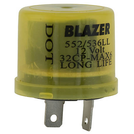
I found that 90% of the time that thermal type flasher units are defective right out of the box new. I buy electronic flasher units for use with incandescent bulbs, something like this one from Tractor Supply.
1780093

For use with LED bulbs, I buy a dedicated LED flasher.
 
The flasher is working, but not consistently. It’s rated for 25 amps so I think that is more than enough for a couple 21W signals. I’m going to start troubleshooting the ground fault today. As ugly as the wiring is I’m sure to find something.
 
So far 3 of 15 wires in the main harness don’t match the colors listed in the schematics... but they look original. The mess really starts in the harness between the 15-pin and the 12-pin connections. One of the turn signal wires had a quick-splice going to a ground point. Yuck.
 
So far 3 of 15 wires in the main harness don’t match the colors listed in the schematics... but they look original. The mess really starts in the harness between the 15-pin and the 12-pin connections. One of the turn signal wires had a quick-splice going to a ground point. Yuck.

Welcome to the world of Guzzi where the documentation is lacking in accuracy. You may have better luck with pin to pin tracing.
 
Just a FYI to anybody who is troubleshooting this type of issue.

I absolutely LOVE these leads which attach to your multimeter. They allow me to send an amperage test down the line to determine resistance.

When it comes to a wire issue, you have 1 of 3 conditions only.

1. Open
2. Short to Ground
3. High resistance.

This fantastic tool makes short work of figuring this out. I highly recommend it.

http://www.esitest.com/180.html

180-3big.webp
 
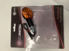
Well I found the main issue with the signals, and it’s the signals themselves. The threaded stalks do not tolerate grounding to the bike, and heat up VERY quickly. The signals work fine when grounded via the integral grounding wires. Rather than buy a different style, I’m just going to isolate the stalks with a plastic bushing or shrink tube and use a Teflon or fiber washer to isolate the nut.
 
Well I found the main issue with the signals, and it’s the signals themselves. The threaded stalks do not tolerate grounding to the bike, and heat up VERY quickly. The signals work fine when grounded via the integral grounding wires. Rather than buy a different style, I’m just going to isolate the stalks with a plastic bushing or shrink tube and use a Teflon or fiber washer to isolate the nut.


Sorry, that doesn't make much sense at all. If the stalks are conducting current, then there is an internal issue with the wiring of the lights. On many signals, the stalk is what provides a ground path for the turn signal bulb as only a hot wire runs to the light. What lights are you attempting to use?
 
I agree; it’s pretty frustrating. All 4 behave the same, though, so I don’t think it’s an internal fault, just a cheaply made Chinese component.

I also removed the battery tray and cleaned up the contact areas and made sure there was metal to metal contact at all connections. There was a lot of paint and some rust. I think that will help with getting a good ground through the frame and engine.

Edit: I am the issue ☹️. The signals have a solid black wire, and a black wire with a white stripe. I assumed the solid black would be ground, as that is what I am used to seeing, and never gave it a second thought. Turns out, the signals have 2 means of grounding: via the stalk, and via the black wire with white stripe. There were no instructions with the signals, or to be found within a reasonable time on the google machine. Whew. We got there eventually.

Thanks all for the assistance and common sense. Now to get the horn working...
 

Attachments

  • 58AB8995-93B1-4047-AFBF-C6A97A704492.webp
    58AB8995-93B1-4047-AFBF-C6A97A704492.webp
    16.7 KB · Views: 8
Last edited:
Edit: I am the issue ☹️. The signals have a solid black wire, and a black wire with a white stripe. I assumed the solid black would be ground, as that is what I am used to seeing, and never gave it a second thought. Turns out, the signals have 2 means of grounding: via the stalk, and via the black wire with white stripe. There were no instructions with the signals, or to be found within a reasonable time on the google machine. Whew. We got there eventually.

Thanks all for the assistance and common sense. Now to get the horn working...

I was suspecting you connected the hot lead to the ground wire. It came to me last night and I was going to post that this morning. Always confirm wiring with an ohm meter, hot lead to bulb center contract Gee, black wire hot, just like house wiring. Be glad you aren't working on a BMW airhead. On those bikes the ground wire is brown!! Glad you found the issue.
 
Back
Top