• Ciao Guest, The owner of this website and GTMotoCycles.com lost his home completely on the morning of January 8th in the L.A. Wildfire Storm. Most of his neighborhood is gone, and a few friends were killed along with their pets. The GTM SHOP and STORE are functioning normally, but we DEMAND EXTREME PATIENCE on orders as we are a SMALL business and Todd usually has his hands on nearly every order before it goes out. You can find more info on a post named L.A. Wildfires in the USA section. Our heart and best go out to everyone in this horrific disaster.

And on to the electrics

haventaclue

Just got it firing!
Joined
Dec 3, 2024
Messages
21
Reaction score
6
Location
Letterkenny Donegal Ireland
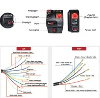
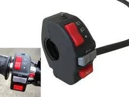
On this bike, half the loom is missing, I tried with the generic loom, that did not go well, in that I couldn't make head nor tail of it. The colours didn't match, no molex blocks would match except for the new control switches.
So I decided to make up one, incorporating the old loom. New fuse box, relays, flasher unit and a bunch of molex blocks I'm going to give it a go.
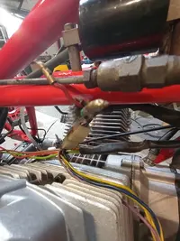
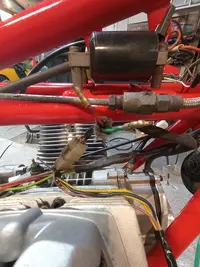
I have the loom for the alternator, rectifier and regulator. I have looked, magnified, zoomed in but can't figure where these two wires do or go, one green, one red with bullet connectors. Could someone please enlighten my fried brain and eyes :(

IMG_20250114_125754694_MFNR.webpIMG_20250114_125801568_MFNR.webp
 
With and account upgrade, you can get the schematic in the downloads section. Also without seeing the origin of the wires can't tell what they are. See;

 
Already donated 16th Dec :)
Those two wires, under the brake pipe connection, thought I had arrowed them, are coming from or going to the alternator . I'm guessing the red is from the battery, having bother with the green, can't see it on the wiring diagram that I have.
 
Last edited:
Although red & green go down to the 'alternator area', they are nothing to do with the alternator, (just run inside same heat shield sleeve) so you won't find them on the wiring diagram near the alternator/rectifier etc. They come from the ignition points (actually connect to the condenser blocks) & go to the coils - shown here where V = green & R = Red.
coils.webp
 
Here is pic of connection at points block (red spade is off but you can see green in place). Note: The 12V supply for this ignition circuit is the White (BI) that comes from the 'infamous' rubbish routing of the ignition feed through the RHS switchgear to the coil common +12V. From the coil common feed, the LT switching is done to earth at the points breaker plate......I've re-routed this (and many other circuits) through new relays to improve reliability.

greenredwires.webp
 
Hold on, mate. I got V50III loom, probably mostly complete. This is after 1982 probably, so not sure if this would fit you, but here it is, I got no plans about it. Can make some pics and investigate how complete it is.
 
Although red & green go down to the 'alternator area', they are nothing to do with the alternator, (just run inside same heat shield sleeve) so you won't find them on the wiring diagram near the alternator/rectifier etc. They come from the ignition points (actually connect to the condenser blocks) & go to the coils - shown here where V = green & R = Red.
View attachment 39117
Thank you, this is what I needed. You're a scholar and a gentleman.👍
 
Hold on, mate. I got V50III loom, probably mostly complete. This is after 1982 probably, so not sure if this would fit you, but here it is, I got no plans about it. Can make some pics and investigate how complete it is.
I have spent over five hours today building a loom, I'm beginning to hate molex blocks and their fiddly connections:rofl:, and trying to follow a wiring diagram that I can hardly make out the letters on. I'll run it past my friend, his baby, but we're moving along..........slowly. Not touching it again until next week. What have you on it?
 
Here is pic of connection at points block (red spade is off but you can see green in place). Note: The 12V supply for this ignition circuit is the White (BI) that comes from the 'infamous' rubbish routing of the ignition feed through the RHS switchgear to the coil common +12V. From the coil common feed, the LT switching is done to earth at the points breaker plate......I've re-routed this (and many other circuits) through new relays to improve reliability.

View attachment 39118
I think I'll take a leaf out of your book and add another relay for the coils.
 
I think I'll take a leaf out of your book and add another relay for the coils.
The less you route power through the ignition switch, the better. Guzzi didn't really start using relays well until the development of the CARC bikes. All other models pass too much current through the ignition switch.
 
Back
Top