• NOTICE: Starting March 24th, we've shifted to a mandatory user Account upgrade (donation) to post here. Once you've created an account, see the SITE SUPPORT section at the bottom on how to upgrade. This is to help try and cover site costs, and reduce redundant and argumentative posts. Search and read before staring a new thread, most topics are well covered here. We still require ONE post in the Intro section (bottom of the main Forum section list) to introduce yourself: NO QUESTIONS THERE - THEY WILL BE DELETED. Small $ donations via our link above will not be considered. Also to NOTE, the owner of this website lost his home in the LA Wildfire storm in January; See the USA section for more details. Your consideration and understanding on use of this site is expected. It's NOT a free social media platform - decades of time and personal money are invested. We have a zero tolerance policy on attacks. Do NOT write us direct and ask questions unrelated to the Forum, we do not offer Tech support direct, they will be deleted.

And on to the electrics

Sorry, I didn't write what I meant, brain fog :(. When I bypass the flasher unit to the wire in the cluster, I have nice bright indicator light, though not flashing.
dbarale, Using stock incandescent bulbs, LED turns on for high beam. I took 12v+ to head light bulb splicing with yellow in the cluster and the yellow from the dash. Flasher unit to grey indicator common and all lights flashed, including the headlight:D, and it's just dawned on me that the LED was not connected. The green wire for the LED is a ground, Paul Brice you may be on to something.
Paul Brice, I didn't know there could be a difference. I will check that out and get a different unit.
I'm going to take a holiday in the sun and forget about it for a few weeks:)
 
Ok I'm back :( .
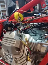
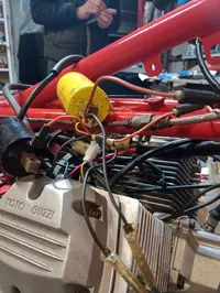
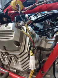
I'm tryin to figure out the coil wiring. This does not make sense to me.
Yellow is left coil, black right. This is how the wires are looped and the only place for the green and red wires coming from the points are the two black bullet connections and nowhere for the white spade connection. Do the coils ground via the bolts to the frame? Or the bullet connections? If that's the case, where do the red and green wire connect? What am I missing?
White spade connection is out of the pic and ignore the rubber bullet insulation as I have replacement.
 

Attachments

  • IMG_20250212_153215397_MFNR.webp
    IMG_20250212_153215397_MFNR.webp
    115 KB · Views: 6
  • IMG_20250212_153244469_MFNR.webp
    IMG_20250212_153244469_MFNR.webp
    106.7 KB · Views: 6
  • IMG_20250212_153251432_MFNR.webp
    IMG_20250212_153251432_MFNR.webp
    99.6 KB · Views: 6
Last edited:
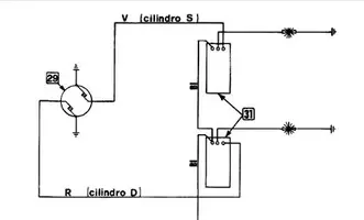
I'm not sure why you aren't talking about the orange wires going to the coils (I can see them in the pics !!!) ??. In OEM set up of coils, the orange wires running into the coils are the common 12V feed. Somewhere near the coils the orange wires connect to a bullet/bullets with the WHITE 12V live feed from the ignition circuit.

This common 12V (Low tension) feed runs through the LT coil windings and comes out as a black wire in both coils (because they are basically the same product)

...somewhere near the coils the black wires go to bullet connectors that connect them to the wires down to the contact breaker plate. These are different colours (RED & GREEN) because they go to different breakers. So.... through the RED wire from the RHS coil black wire bullet connection & through the GREEN wire from the LHS coil black wire connection. The RED and GREEN wires run to EARTH through the contact breaker & each fires (goes to earth) at different point in lobe rotation.

NO the big piece of metal in the coil is not an Earth for the LT circuit, but it helps generate big magnetic fields to generate the current in the HT circuit/coil & it is an earth for residual current generated by the collapsing magnetic fields inside the metal.
 

Attachments

  • coil wiring.webp
    coil wiring.webp
    7.3 KB · Views: 0
and in case it helps a bit more, here is an OEM coil currently on ebay. You can clearly see the common 12V feed orange wire & the black 12V output wire that would connect to either RED or GREEN wire (depending which side of bike you fit it !) down to the breaker.

You can also see that the ORANGE wire has two bullets/spade connectors; one will be for common 12V feed & the other to go to other coil.

As always, beyond the black & orange wires which are moulded into the OEM coil, any other colours of wiring may have been used in re-wiring over the years. Other coils may have different colours but usually BLACK is the output to breakers wire.oem coil.webp
 
Thanks to all for the advice, electrics, lights and indicators sorted, except the high beam warning light comes on when the dip is on and goes off when switched to headlight. I'll figure it out, I hope :), also faulty front brake switch.
So now back to the clutch which I put on the long finger.
 
Wired high to low and vice versa.
Well I cracked and we're out sourcing the gear box and clutch rebuild, and got a nice list of expensive bits:cry:. And I think that's the best thing to do. So list ordered except for nuts for gear main shift, whatever they are, and not sure when it will be ready.
 
Back
Top