• Ciao Guest - You’ve landed at the ultimate Guzzi site. NEW FORUM REGISTRATIONS REQUIRE EMAIL ACTIVATION - CHECK YOUR SPAM FOLDER - Use the CONTACT above if you need help. New to the forum? For all new members, we require ONE post in the Introductions section at the bottom, in order to post in most of the other sections. ALWAYS TRY A SEARCH BEFORE STARTING A NEW TOPIC - Most questions you may have, have likely been already answered. DON'T BE A DRIVE-BY POSTER: As a common courtesy, check back in and reply within 24 hours, or your post will be deleted. Note there's decades of heavily experienced Guzzi professionals on this site, all whom happily give endless amounts of their VALUABLE time for free; BE COURTEOUS AND RESPECTFUL!
  • Be sure to see the GTM STORE link also above for our 700+ product inventory, including OEM parts and many of our 100% Made-in-SoCal-USA GTM products and engine kits. In SoCal? Click the SERVICE tab above for the best in service, tires, tuning and installation of our products or custom work, and don't miss our GT MotoCycles® (not) art on the BUILDS tab above. WE'RE HERE ONLINE ONLY - NO PHONE CALLS MADE OR RECEIVED - DO NOT EMAIL AND ASK QUESTIONS OR ASK TO CALL YOU.
  • There is ZERO tolerance on personal attacks and ANY HYPERLINKS to PRODUCT(S) or other competing website(s), including personal pages, social media or other Forums. This ALSO INCLUDES ECU DIAGnostic software, questions and mapping. We work very hard to offer commercially supported products and to keep info relevant here. First offense is a note, second is a warning, third time will get you banned from the site. We don't have the time to chase repeat (and ignorant) offenders. This is NOT a social media platform; It's an ad-free, privately funded website, in small help with user donations. Be sure to see the GTM STORE link above; ALL product purchases help support the site, or you can upgrade your Forum profile or DONATE via the link above.

NTX350 Charging problem

Jimmy The Web

Just got it firing!
GT Contributor
Joined
May 31, 2024
Messages
13
Location
Irvine, Scotland,United Kingdom
Hi all,

First post on electrical charging problem with my recently acquired NTX350. Bike is in good condition and starts OK but charging warning light stays on.
I am new to this type of charging system ( my 1988 Tenere XT600 3AJ uses permanent magnets).

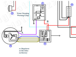
I have attached the relevant part of the circuit diagram I am using.

I have taken the following measurements:

Field Coil Resistance 3.9 ohms
Charging bulb resistance 14.3 ohms measured back to battery positive.
3 phase winding to winding 0.8 ohms (same across all phases)
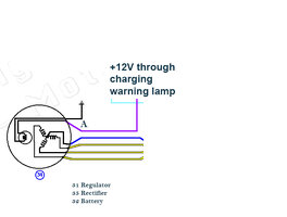
Votltage at point B with ignition on and engine not running 12V
Voltage at point A with ignition on and engine not running 0.46 V

My understanding is that the circuit through the charging lamp to the regulator should initially provide sufficient current to excite the field coil to produce the magnetism to generate the 3 phase AC. As engine runs and AC increases the rectified voltage increases to a certain voltage (14 V say) the regulator stops supplying current to the field coil.

My problem is that I am getting no 3 phase output with the engine running.

The voltage at pont A could be calculated as the ratio of the resistances of the field coil and the charging warning lamp less any voltage drop across the regulator internal transistors and diodes (say 2.1V across 3 off 0.7V junction drops) so should be around (12-2.1) x (3.9/14.3+3.9)) = 2.12V

I am only seeing 0.46 V at point A

If I disconnect the wire from the regulator going to the Field coil +ve I see 5.6 V on the wire

If I connect +12V momentarily straight across the field coil, the 3 phase windings generate 3 phase power no problem with the engine running.

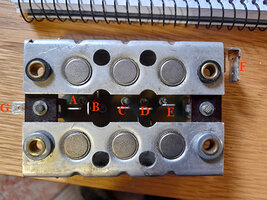
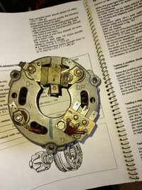
Also I am a bit surprised that one half of the rectifier diode board is at +12V and the other half is floating. The circuit diagram shows the casing as earthed, but I cannot see a terminal on the board to connect the earth to. I have attached a pic of what I believe are the connections to the diode board.

A and B - feed from warning lamp to regulator (connected together)
C,D and E - 3 phase input
F - rectifier output to battery
G - star point from stator windings.

I am a bit lost here, can someone please help.

Thanks,

Jim
 

Attachments

  • bared2.png
    bared2.png
    1.3 MB · Views: 12
  • Forum Electrical 1.jpg
    Forum Electrical 1.jpg
    146.6 KB · Views: 12
  • rectifier diode board.jpg
    rectifier diode board.jpg
    205.3 KB · Views: 13
Wish I had a better view of your alternator, but from the picture of your regulator it is the Bosch system. Did you test the rotor? Lift a brush and get the resistance of the rotor windings. It should be 3.4 ohm +/- 10%. Stator readings are in range. To test the system, disconnect the regulator and jumper the red and purple connectors. System should charge. If it does, the regulator is bad. If it doesn't there is a different issue. Let us know what you discover. Fortunately many parts are common to BMW airheads except the rotor. I believe the crankshaft taper is different.
 
Wish I had a better view of your alternator, but from the picture of your regulator it is the Bosch system. Did you test the rotor? Lift a brush and get the resistance of the rotor windings. It should be 3.4 ohm +/- 10%. Stator readings are in range. To test the system, disconnect the regulator and jumper the red and purple connectors. System should charge. If it does, the regulator is bad. If it doesn't there is a different issue. Let us know what you discover. Fortunately many parts are common to BMW airheads except the rotor. I believe the crankshaft taper is different.
Hi John,

Thank you very much for replying. I really appreciate it.

I have attached a better image of the stator. I do think it is a Bosch component.

I have tried disconnecting the regulator and shorting the red and purple, but with similar voltage across the field coil and no 3 phase output.

What I will try next is to take everything I can out of the equation:

I will disconnect the regulator, and jumper red and purple, also disconnect the rectifier completely but jumper the connections so that the circuit looks like "reduced circuit" attached. I have a concern that both the regulator and rectifier may be faulty, and just want to check the basics.

I will let you know how this goes.

Thank you again
 

Attachments

  • reduced circuit.jpg
    reduced circuit.jpg
    91.3 KB · Views: 4
  • Stator  1.jpg
    Stator 1.jpg
    127.3 KB · Views: 4
Bolting the diode board to chassis is the ground. If you take the diode board out, look for AC current out of the stator to ground, but I think you already know this. You could rig up a test bulb(s) to connect to the stator outputs as well. It is how we test a Motel T Ford magneto that outputs AC voltage.
 
The ground is provided by the mounting bolts. The rubber was for vibration degradation which BMW believed was happening, when in fact it was component soldering.

The link I gave you above will give you everything you need including full procedures for testing the diode board.

The answer to all the problems from the rubber mounts, with or without some or all of the BMW grounding wires, are to replace the rubber mounts with solid metal aftermarket mounts, which have additional grounding benefits as well as lasting forever ...& they remove more heat from the diode board heat sink areas, ...which might add to diode board life. “
 
Euromotor Electrics sells the solid diode board mounts as well.

I believe they are the same threads as Moto Guzzi but email them and they will get you right as rain.

Fairly certain you have experienced a diode board failure.

IMG_7394.png IMG_7395.png IMG_7396.png
 
Scott, the way the Guzzi diode board is mounted there are no stand offs for the diode board. It is bolted directly to frame components. Mounting is completely different from a BMW airhead.
 
Scott, the way the Guzzi diode board is mounted there are no stand offs for the diode board. It is bolted directly to frame components. Mounting is completely different from a BMW airhead.

Yes, like the board I showed in #3. I understand.

IDK a V35 in particular, but I was trying to point to a proximate cause, the diode board, and a replacement option and testing documentation.

The standoffs are just one of the ways to mount with a more reliable ground circuit.

The link to the testing information explained it all.

If he wanted to read the process for testing the diode board and the specifications he should be receiving, that is what I am trying to convey.

They should be the identical setup and test out the same AFAIK. (presume)
 
Last edited:
Yes, like the board I showed in #3. I understand.

IDK a V35 in particular, but I was trying to point to a proximate cause, the diode board, and a replacement option and testing documentation.

The standoffs are just one of the ways to mount with a more reliable ground circuit.

The link to the testing information explained it all.

If he wanted to read the process for testing the diode board and the specifications he should be receiving, that is what I am trying to convey.

They should be the identical setup and test out the same AFAIK. (presume)
Yes diode board test is the same. Mounting is completely different as it is on the side of the frame far from heat sources. If the BMW type stand offs were used, you probably couldn't get the side cover on the bike as the diode board would stick out too far.
 
Thanks for the feedback. I read Snowbums very comprehensive article on the diode board mounting and testing, and am comfortable with testing the diodes with a meter. I will post pics of the mounting bolts and mounting position later.

Can you confirm that the top half of the body of the diode board is connected to
+12 v and the bottom half of the board body to chassis.

Also does anyone know what current I should be seeing through the field coil via the charging warning lamp and regulator at startup

Thanks Jim
 
Attached is a pic where the diode board is mounted - on the plastic splash guard just behind the battery tray.

I still cannot understand how the mounting bolts are meant to earth it, and the positive feed to the battery is connected to the body of the diode board??. I understand the circuit, but cannot get my head round how it is meant to be mounted properly (isolated??), and if additional earth wires are necessary - confused!!!

I have ordered a new battery, to rule it out as an issue.

The first test with the new battery will be with a 1.3 W bulb in line straight to the +ve end of the field coil. No other connections to rectifier or regulator. Engine running of course

I expect this to output at least a small amount of AC between each phase and the WYE starpoint (and a lit bulb)

Am I doing the correct thing here?

Thanks Jim
 

Attachments

  • diode board mounting 1.jpg
    diode board mounting 1.jpg
    430.9 KB · Views: 3
I have never worked on your specific model of motorcycle.

Is that the OEM mounting location? If so, perform a continuity test between the diode board mounting bolts and the frame of the motorcycle. There should be continuity if the bolts are inserted correctly.

Do you have a manual?
 
On Tonti framed bikes, it mounts to the frame of the bike. Add a ground wire underneath where the bolt goes through and that will supply a ground for the frame of the diode board.
 
I have never worked on your specific model of motorcycle.

Is that the OEM mounting location? If so, perform a continuity test between the diode board mounting bolts and the frame of the motorcycle. There should be continuity if the bolts are inserted correctly.

Do you have a manual?
Hi Scott,
I have no documentation tthat shows the physical mounting or earth wires. The circuit diagram shows that the unit is connected to ground (as I have been told, through the mounting bolts) but the positive output terminal from the rectfier to the battery positive tterminal seems to be connected to the rectifier body. So why no shorting problem??

I'm just not getting the part that the rectifier body, and mounting bolts play in the circuit, especially the positive connection to the battery. The rectifier body can't both be connected to earth and the battery positive.!!!

Sorry for being slow here!

Thanks for your patience and help.

Jim
 
No worries.

I haven’t worked on a diode board BMW for about 25 years and my notebooks are buried in my workshop full of boxes so my memory is sketchy.

IMG_7403.jpeg


I cannot remember what the + post F looks from the side and back, but I thought for sure that it was insulated from the main housing. (There used to be 2 non-conductive rivets that held it onto the main body I thought.)

Did you check continuity from the post to the housing? 2 seconds check with a multimeter.

If you can, take pictures from all sides and post here so we can see everything.

There are V35 manuals in the DOWNLOADS section.

If you upgrade your account to a Contributing Member (I think it is a one time minimum $25 donation to the site operations cost) then you can access everything there.

Besides, it also helps keep the site free of all the obnoxious advertising so prevalent on sites nowadays.

I am on my way home now, and I will also check my Guzziology manual to see what I can find to help you out.
 
Last edited:
Back
Top