• Ciao Guest - You’ve landed at the ultimate Guzzi site. NEW FORUM REGISTRATIONS REQUIRE EMAIL ACTIVATION - CHECK YOUR SPAM FOLDER - Use the CONTACT above if you need help. New to the forum? For all new members, we require ONE post in the Introductions section at the bottom, in order to post in most of the other sections. ALWAYS TRY A SEARCH BEFORE STARTING A NEW TOPIC - Most questions you may have, have likely been already answered. DON'T BE A DRIVE-BY POSTER: As a common courtesy, check back in and reply within 24 hours, or your post will be deleted. Note there's decades of heavily experienced Guzzi professionals on this site, all whom happily give endless amounts of their VALUABLE time for free; BE COURTEOUS AND RESPECTFUL!
  • There is ZERO tolerance on personal attacks and ANY HYPERLINKS to PRODUCT(S) or other competing website(s), including personal pages, social media or other Forums. This ALSO INCLUDES ECU DIAGnostic software, questions and mapping. We work very hard to offer commercially supported products and to keep info relevant here. First offense is a note, second is a warning, third time will get you banned from the site. We don't have the time to chase repeat (and ignorant) offenders. This is NOT a social media platform; It's an ad-free, privately funded website, in small help with user donations. Be sure to see the GTM STORE link above; ALL product purchases help support the site, or you can upgrade your Forum profile or DONATE via the link above.
  • Be sure to see the GTM STORE link also above for our 700+ product inventory, including OEM parts and many of our 100% Made-in-SoCal-USA GTM products and engine kits. In SoCal? Click the SERVICE tab above for the best in service, tires, tuning and installation of our products or custom work, and don't miss our GT MotoCycles® (not) art on the BUILDS tab above. WE'RE HERE ONLINE ONLY - NO PHONE CALLS MADE OR RECEIVED - DO NOT EMAIL AND ASK QUESTIONS OR ASK TO CALL YOU.
  • Like the new V100, GuzziTech is full throttle into the future! We're now running on an all-new server and we've updated our Forum software. The visual differences are obvious, but hopefully you'll notice the super-fast speed. If you notice any glitches or have any issues, please post on the Site Support section at the bottom. If you haven't yet, please upgrade your account which is covered in the Site Support section or via the DONATE tab above, which gives you full site access including the DOWNLOADS section. We really appreciate every $ and your support to keep this site ad-free. Create an account, sign in, upgrade your account, and enjoy. See you on the road in 2024.

Specification red LED in Norge/Breva Taillight

Hi all,

Thank you for your great support on this topic.
This is where I'm at:
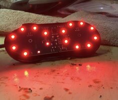
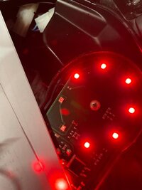
- did some initial electronic measurements on the PCB, and one of the earlier dead LED's fired up; made me thinking that the LED's themselves are not the issue;
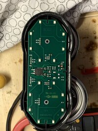
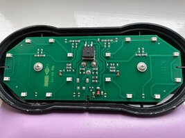
- the PCB is organised such that left and right LED's are mirrored in terms of their electric feed;
- the 8 (per side) LED's are fed in 2 strings of 3 LED's and 1 string of 2 LED's;
- the string of 2 LED's is the problem area;

Currently working my way through some fault analyses on the circuit with a more knowledgeable friend.
I'll keep you posted on the progress and share the electronic schema once done.

I've attached a picture of the PCB and the PCB functioning in "brake-mode".

Jan
 

Attachments

  • MG Taillight01.jpg
    MG Taillight01.jpg
    99.3 KB · Views: 4
  • MG Taillight02.jpg
    MG Taillight02.jpg
    94.5 KB · Views: 4
Can you post photos of the PCB? It would help to know if the current limiting is done resistively on the PC board itself or if somehow a different module on the bike is responsible for that.

If the current limiting is done on the PC board, I would suggest getting a cheap 3A adjustable bench supply and ordering an assortment of LEDs from Mouser with the appropriate package, and double the brightness with each different part number. Presuming these are all surface mount parts, you can just touch each one to the PCB hooked up to a bench supply to find one that's about as bright as the others, then you'll know what you need.
Added some photo's of the PCB in my last post
 
Sure
Also the Power transistors is B44H11G from ON and their data sheet is as attached. The circuit for each half is split into 3 individual circuits , 2 off with 3 LEDs and another with 2. The 3 LED cct has 2 serial resistors of 47 Ohm each giving a reistance of 94 ohms. the 2 LED cct has 2 of 150 Ohm in parallel giving a reistance of 75 OHMS (thats the easy bit)
Emitter base voltage is 5v it seems.
i'Il look a bit more but this seems a relatively simple circuit. If you get single LED failing then yes its an LED failure, if like me you have 2 on the same circuit then it could also be something elses such as the IN4148 diode in the cct being a bit duff (least that may be)
Ill look again later but if you want to progress this please do.
Katie
(didnt see the previous post..)
 

Attachments

  • circuit 1.jpg
    circuit 1.jpg
    138.3 KB · Views: 2
  • KA-3535SEL2Z4S LED Data Sheet (1).pdf
    179.4 KB · Views: 1
Last edited:
This was mine on the same part of the cct. something going through them as they are lightly activated but not much.
Maybe there is a weakness in this area if lots of us are getting issues here.
Alternatively just resoldering as if this was in an area where the PCB prep prior to the automated soldering process was undertaken then that might help. Ill have a go with touching up the joints tomorrow but its almost 40 years since I worked on SMDs lol.. Or one of the load resistors is faulty, you never know.

Katie
 

Attachments

  • fails.jpg
    fails.jpg
    48.4 KB · Views: 2
Last edited:
Now this topic is fascinating and really good gold-standard information! Please keep it coming!

Whatever you do, please don’t just resolve your problem and not share it fully with the GuzziTech community. 🤞👍😄
 
Well nothing about this is going to be the "easy way"! How I suspect this works is there's a pulse-width modulated signal going to the base of that chunky transistor, and it is varying duty cycle to determine brightness. I had hoped there would just be a bright string and a dim string instead.

Surface mount LEDs themselves are incredibly moisture sensitive. When we get them at work, they are sealed in a bag with a desiccant pouch and there's a piece of paper that will turn colors as the moisture they are exposed to increases. Beyond a certain point they have to be baked at a low temperature to dry them out before soldering or they will fail when being installed. That's a long explanation for why you may be having issues once moisture gets in, and also to show why any that you remove from the board may be destroyed in the process.

If the part number posted above isn't correct, you could take calipers and measure the size of the units you have, then reference this chart:
https://en.wikipedia.org/wiki/SMD_LED

My best guess would be these: https://www.kingbrightusa.com/product.asp?catalog_name=LED&product_id=AA3527ASESK/J3-50MAV

There's another part they make that's slightly less bright.
 
For that pair of LEDs that aren't working, you can measure the resistance of the loading resistor behind those.
Tail light

If you try to measure DC voltage being applied to the LEDs themselves and PWM is being used to control their brightness, you'd really need a scope to understand what's going on. If you look at the yellow arrow I have, the red with black stripe under it is a zener diode and is intended (probably) to mimic a third LED without putting off any light. If that sucker came loose on one end, that would cause the two LEDs below it to no longer light up. That particular package isn't the most likely to stay put IMO.
 
I agree. gently resoldering them may remove any dry or compromised joints though and Ill try that first. All the resitors do is indeen not only condition the supply but also mimic the third LED. Yes, I could measure the resistance of the 150 OHM reisitors but only out of circuit as you say. Hence just replace them. Ill try soldering first. I have time as My S1000XR also needs riding ;)
make sure you clean off the edge sealant on both parts properly. I wont drill holes in the mouldings as that lets moisture in as well as out, Id prefer to put a small bag of silicone (despite its issues) in a secure place between the board and the reflector moulding. I can always replace in 5 years if needed.
katie
 
And yes the 4148 is a Zener Diode.. Very common SMD. the resistors are 150 Ohm as stated. they are so OP for this application I would not expect them to fail at all but easy way is to measure the voltage after them to the return rail. If we have a 5V supply then they will show a 3v or so reduction (from my old and whisky/gin inspired brain - was a long time ago..), or maybe 2v ish. Someone who has done the maths needs to check this out I think. Im asking a friend but she is partying in Leeds all weekend..... (More lost brain cells) - wish I was there :)
Dry solder joints or contaminated joints make for high or variable resistance esp regarding temperature as Im sure you know. Dry the board out (Oven at 40C max for 12 hours but dont blame me if anything bad happens (dont use silica as it can contaminate the joints) and then resolder as a minimum if you dont know how to properly remove solder with braid, just apply heat very locally until the solder shines and remove heat. You need a very fine point soldering iron and NO PRESSURE!!! it melts when it can so dont hurry it.. SMD boards were given a life of 5+ years in the 1990's so they could repair or resell equipment. these are 13+ years old. Try Solder iron at 300F and work up to 340F, only touching for like half a second max to see if the solder melts. Too long or too high heat will fry the component - or try lower but needs to be only a quick touch so the heat doesnt get into the device. You do it at your own risk of course as it depends on the solder used and my comments are for 60/40 solder (usual hand solder spec and I have no idea what spec solder was used to make these). no flux at all if touching. Changing a component is a differennt story as any flux used needs to be completely removed and never use old solder in your tool box as you dont know its flux content.. just saying - all at your risk again of course.
Katie
 
Last edited:
And if you are wondering if I know what im talking about, look me up on LinkedIn (Katie Taylor) - Work for Alstom atm. Unfortunately Im a manager and I need the Guzzi to get me thinking about engineering again. I think I need to build a MG special at some time.... lets see but funds prohibit atm.. TC all (wear a mask and get vaccinations - not microchips or mind control drugs - yet lol)
 
Notice they have shorted out a big part of the LED so its an over spec LED with the bypass circuit (tell me if Im wrong) internal part bypassed. Ill post a cct diag but it looks like a more basic SMD LED may be usable..
 
I'd recommend a cheap hot air station for stuff like this. An iron can't really get both ends of the component hot at the same time so it will pop off cleanly. Is there anything on the other side of the board? I guess I'm curious if there's a PWM signal being sent to the tail light or just a +12 for running and a different +12 for brake and that is somehow being used to change the brightness with a single transistor.
 
Disagree. Irons allow for pin point heat. Hot air fukz everything in its path... Tell me im wrong but I did and managed a section soldering and repairing SMD (1980s GEC UK so far above the Chinese until the financiers found something better.. pity otherwise we would be where the US and China are for then now+) .. but we were so much better and world beaters (Kidgsgrove) ,,, Ex has 20 years rework exp so Ill ask them xx
Its a standard component but there will be cheaper alternatives as Italian's are cheap Arses with old Guzzis and Dukes. one fingered to older ones it seems
Katie
 
I'm not a huge fan of hot air either, especially when the part you're trying to solder gets blown off from where you put it. Still for getting heat on lots of pads I can't manage with an iron :/
 
Its a standard component but there will be cheaper alternatives as Italian's are cheap Arses with old Guzzis and Dukes. one fingered to older ones it seems
Katie
No. Not at all. It's simply a numbers game. If a unit is produced in large numbers, then there will be a larger supply of parts made because of the basic business premise of the economy of scale.

Italian manufactures are not giant number sales. They are a niche market. Moto Guzzi is the very definition of "boutique" builder. Piaggio as a company is not, but Moto Guzzi is. They are simply limited by the physical size of the factory, but the level of demand does not warrant the giant cost and incredible government headache it would be to try and get permission to move the factory. The Italian government will never grant that exemption ever. I guarantee it.

So, there simply is a limited amount of cross use of the same part, and those which are rather unique, are made in less quantities most likely.

I am curious, is this a "bugs me when I look at it" kind of problem, or a "the damn motorcycle will fail the INSPECTION " kind of problem, or is it both?

BTW: You guys lost me way back there, but it's fun to read and try and understand. Lots of Googling of technical terms. :think: :D
 
Last edited:
I'd recommend a cheap hot air station for stuff like this. An iron can't really get both ends of the component hot at the same time so it will pop off cleanly. Is there anything on the other side of the board? I guess I'm curious if there's a PWM signal being sent to the tail light or just a +12 for running and a different +12 for brake and that is somehow being used to change the brightness with a single transistor.
Indeed, just +12v for running and +12v for braking. I’ll try the resoldering first and currently sourcing that 4148 diode.
 
No. Not at all. It's simply a numbers game. If a unit is produced in large numbers, then there will be a larger supply of parts made because of the basic business premise of the economy of scale.

Italian manufactures are not giant number sales. They are a niche market. Moto Guzzi is the very definition of "boutique" builder. Piaggio as a company is not, but Moto Guzzi is. They are simply limited by the physical size of the factory, but the level of demand does not warrant the giant cost and incredible government headache it would be to try and get permission to move the factory. The Italian government will never grant that exemption ever. I guarantee it.

So, there simply is a limited amount of cross use of the same part, and those which are rather unique, are made in less quantities most likely.

I am curious, is this a "bugs me when I look at it" kind of problem, or a "the damn motorcycle will fail the INSOECTION " kind of problem, or is it both?

BTW: You guys lost me way back there, but it's fun to read and try and understand. Lots of Googling of technical terms. :think: :D
Hi Scott, for me this is a “bugs me when they look at it”. We were on a roadtrip to Germany- France-Switzerland with 1 HD, 3 BMW’s and 4 Guzzi’s! I just can’t stand the BMW drivers making fun on the failing LED 🥺
 
I would laugh right back at them and say…

“Moto Guzzi has a LED go out after many years while BMW specialized in R1100 gearboxes that spectacularly grenaded, final drives on R1200’s that burst into flames while riding, crimped upper front forks that came apart and snapped in midflight, surging engines of the F series, R1250 rear brakes so badly ‘German Engineered’ that they locked up on the new bike sales floor, ABS I II III failures galore…

Oh yes, BMW…so much better than those funny little Italian motorcycles from Mandello del Lario with a couple burned out LED’s…

I THINK NOT!”
 
Found the packet I was looking for the LEDs are made by AVAGO Technologies and the part number I have is this
HSMJ-A401-T40M1
LED, SMD, PLCC4 Red
I did a quick Google and found a few on ebay as well as other sites, prices have gone up a lot - I bought 5 in 2017 and they were £5.74 ukp :( other sites seem cheaper

not sure if this link will help (or show) Removed the leading stuff

ebay.co.uk/sch/i.html?_from=R40&_trksid=p2380057.m570.l1313&_nkw=AVAGO+TECHNOLOGIES+-+HSMC-A401-U80M1+-+LED%2C+SMD%2C+PLCC4%2C+RED&_sacat=0
 
Back
Top